In the world of structural engineering, few systems offer the elegant efficiency and robust performance of the rigid frame. This fundamental structural concept, where beams and columns are connected with moment-resisting joints, creates a singular, monolithic unit capable of withstanding significant loads. Its inherent strength and clean architectural lines have made it a cornerstone of modern construction, from vast industrial warehouses and soaring aircraft hangars to sophisticated commercial buildings and expansive sports arenas. By eliminating the need for numerous interior supports, rigid frame design unlocks vast, column-free spaces, offering unparalleled flexibility for occupancy and use. This introduction explores the key principles that govern its design, its diverse applications across industries, and the compelling advantages that continue to make it a preferred choice for engineers and architects seeking both form and formidable function.
Understanding Rigid Frame Structures in Modern Engineering
Understanding Rigid Frame Structures in Modern Engineering
A rigid frame structure, also known as a moment-resisting frame, is a fundamental structural system where beams and columns are connected with rigid, monolithic joints. Unlike pin-jointed or simply supported systems, these connections are designed to transfer both shear forces and bending moments, creating a continuous load path. This inherent continuity is the defining characteristic that allows the frame to resist lateral and vertical loads through frame action, without relying solely on diagonal bracing or shear walls.
The core principle lies in the joints’ ability to maintain the original angles between members under load. When subjected to forces such as wind or seismic activity, the entire frame deforms as a single unit. The columns and beams bend, developing internal moments that counteract the applied loads, thereby providing stability and limiting sway. This behavior makes rigid frames exceptionally effective for managing dynamic forces and ensuring structural integrity in multi-story buildings and long-span structures.
Key design considerations for modern rigid frames include:
- Material Selection: Primarily constructed from structural steel or reinforced concrete, each offering distinct advantages in strength, ductility, and construction methodology.
- Joint Detailing: The design and reinforcement of beam-column connections are critical, as they are the focal points of stress concentration and must ensure full moment transfer.
- Load Path Analysis: Engineers must meticulously analyze the continuous path of forces from the point of application down to the foundations.
In contemporary practice, the application of rigid frames is ubiquitous. They form the skeleton of commercial office towers, industrial warehouses, institutional buildings like schools and hospitals, and long-span structures such as aircraft hangars and sports arenas. Their primary advantage is the provision of large, column-free interior spaces, offering unparalleled flexibility for architectural layout and future modifications. Furthermore, their ductile behavior—particularly in steel frames—provides a crucial safety margin in seismic zones, as the frames can absorb and dissipate significant energy through controlled yielding at the joints.
The evolution of this system continues with advanced modeling software and performance-based design, allowing for more optimized, resilient, and material-efficient structures that define modern skylines.
Core Components and Materials for Rigid Frame Construction
Core Components and Materials for Rigid Frame Construction
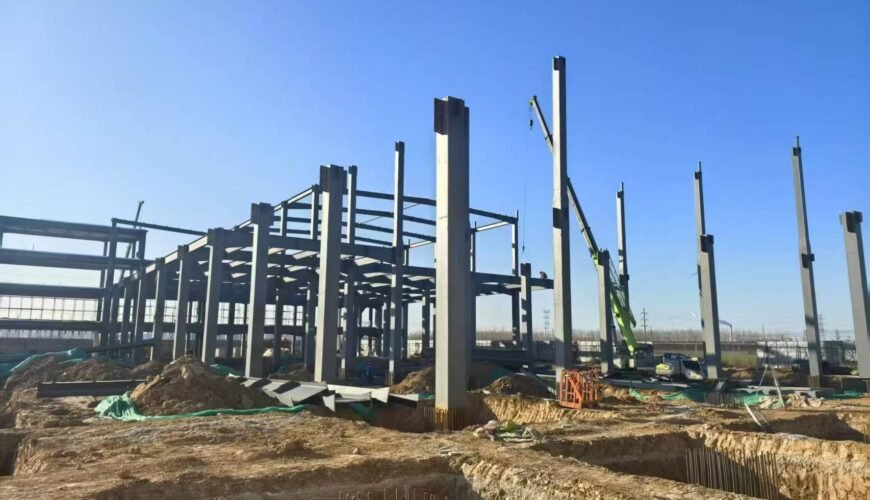
The structural integrity and performance of a rigid frame building are derived from the precise engineering of its primary components and the materials from which they are fabricated. The system is defined by its monolithic connections, where beams and columns are rigidly joined to form moment-resisting joints. This configuration transfers both shear and bending moments, eliminating the need for diagonal bracing and creating large, clear-span interior spaces.
The primary structural members are the columns and rafters. Columns are typically vertical or near-vertical elements that provide vertical support. Rafters, which function as the roof beams, span between columns and are designed to carry roof loads. The critical element is the rigid connection itself, often achieved through full-penetration welds or the use of high-strength bolted end-plate connections. These joints are engineered to maintain their angular geometry under load, enabling the entire frame to act as a single, stable unit.
Material selection is paramount, with structural steel and reinforced concrete being the dominant choices.
- Structural Steel: The most common material due to its high strength-to-weight ratio, ductility, and fabrication precision. Steel frames are typically erected from hot-rolled wide-flange sections (I-beams) for columns and rafters. The material’s consistency allows for the fabrication of complex, rigid connections in a controlled shop environment before rapid on-site assembly. Steel is often protected with fireproofing coatings or encasement.
- Reinforced Concrete: Used for cast-in-place or precast frames. The monolithic nature of concrete is inherently suited to creating rigid joints. Reinforcement detailing at the beam-column junction is critical to ensure moment resistance. Concrete frames offer inherent fire resistance and mass but require careful consideration of formwork and curing times.
Secondary elements, while not part of the primary moment frame, are essential for system completion. These include:
- Purlins and Girts: Cold-formed steel Z or C sections that span between rafters and columns, respectively, to support the roof and wall cladding.
- Bracing: Although the rigid frames resist lateral loads in their plane, secondary bracing is often installed in the orthogonal direction or for stability during construction.
- Foundation Systems: Designed to anchor the rigid frame and resist the significant moments and shear forces transferred from the columns. Spread footings or pile caps are common, requiring careful analysis of overturning forces.
The selection of components and materials is a direct function of the design loads, desired spans, architectural requirements, and economic considerations, with the rigid connection remaining the defining feature of the system.
Applications of Rigid Frames Across Industries and Projects
Applications of Rigid Frames Across Industries and Projects
The inherent strength and clear-span capability of rigid frame structures make them a cornerstone of modern construction. Their primary advantage lies in the monolithic connection between beams and columns, which resists bending moments and creates highly efficient, column-free interior spaces. This fundamental characteristic drives their widespread adoption across diverse sectors.
In commercial and industrial construction, rigid frames are the default solution for warehouses, distribution centers, and manufacturing facilities. The need for unobstructed floor space to accommodate storage racks, assembly lines, and heavy machinery is perfectly met by these systems. Similarly, big-box retail stores and aircraft hangars utilize long-span rigid frames to create vast, flexible interiors essential for their operations.
The agricultural sector relies heavily on rigid frame design for machinery storage buildings, equestrian arenas, and large-scale crop storage facilities. The structures provide the necessary clear height and span to house modern farm equipment while offering durability and relatively low maintenance—critical factors in agricultural economics.
For community and recreational facilities, such as gymnasiums, indoor swimming pools, and community centers, rigid frames deliver the large, open volumes required for athletic and social functions. The design also allows for cost-effective integration of clerestory windows or skylights, enhancing natural lighting.
In specialized industrial applications, including wastewater treatment plants, power generation facilities, and mining structures, rigid frames provide the robust framework needed to support heavy loads, conveyors, and process equipment. Their predictable behavior under load is a key safety and performance factor in these demanding environments.
The adaptability of the system is further demonstrated in architectural projects where aesthetic expression is paramount. By manipulating the frame’s geometry—using tapered columns, varying roof pitches, or curved members—architects can create visually striking terminals, auditoriums, and exhibition halls without sacrificing structural integrity. This fusion of form and function underscores the rigid frame’s enduring relevance from purely utilitarian to landmark architectural projects.
Advantages and Limitations of Rigid Frame Systems
Advantages and Limitations of Rigid Frame Systems
Rigid frame systems, characterized by their monolithic connections between beams and columns, are a cornerstone of modern structural engineering. Their design offers distinct benefits but also presents specific constraints that must be carefully evaluated for each project.
Advantages
The primary advantage of a rigid frame is its inherent moment resistance. The rigid, often welded or cast-in-place, connections allow the frame to transfer and resist bending moments, shear forces, and axial loads efficiently. This creates several key benefits:
- Superior Structural Integrity and Redundancy: The continuity within the frame provides excellent resistance to progressive collapse. Loads are redistributed through multiple paths if a local failure occurs, enhancing overall building safety.
- Significant Clear-Span Capability: By eliminating the need for intermediate columns or bracing in many applications, rigid frames create large, unobstructed interior spaces. This is invaluable for warehouses, aircraft hangars, sports arenas, and industrial facilities where open floor plans are critical.
- Architectural Flexibility: The clean, column-free interiors and the ability to shape the frame itself (e.g., tapered columns) offer architects greater freedom in form and facade design.
- Efficient Lateral Load Resistance: The frame acts as its own lateral force-resisting system, effectively handling wind and seismic loads without relying solely on separate shear walls or braced frames. This integration often leads to a more efficient use of materials.
Limitations
Despite their strengths, rigid frames are not a universal solution. Their limitations are primarily rooted in the complexity of their structural behavior and construction.
- Foundation Sensitivity: The development of end moments in columns transmits significant overturning forces to the foundations. This necessitates robust, often more extensive and expensive, foundation systems, particularly in poor soil conditions.
- Complex Analysis and Design: The indeterminate nature of rigid frames requires sophisticated computer analysis to accurately model member forces, joint stresses, and deflection profiles. This increases design time and cost.
- Susceptibility to Differential Settlement: Any uneven settlement of the supports induces secondary stresses in the frame, which can be detrimental. A rigorous site investigation and foundation design are therefore non-negotiable.
- Constructability and Cost Considerations: Achieving true moment-resisting connections in the field—through precise welding, complex formwork, or post-tensioning—is labor-intensive and requires high-quality control. This can make them less economical for low-rise or simple structures compared to pin-connected or braced alternatives.
In summary, the decision to employ a rigid frame system hinges on a balance between the need for expansive, flexible space and the willingness to invest in sophisticated engineering and robust construction to manage its inherent forces and complexities.
Design Considerations and Best Practices for Rigid Frames
Design Considerations and Best Practices for Rigid Frames
The structural efficiency of a rigid frame is contingent upon meticulous design and execution. Key considerations begin with a comprehensive analysis of loads, including dead, live, wind, seismic, and thermal forces. The inherent moment resistance at beam-column joints makes the frame sensitive to differential settlement; therefore, a robust geotechnical investigation and foundation design are non-negotiable to prevent detrimental induced moments. Lateral stability is a primary function, requiring careful attention to the frame’s sway under horizontal loads. Engineers must analyze and detail connections to develop the full moment capacity while ensuring constructability.
Material selection dictates detailing and performance. For steel frames, focus on connection design—using fully restrained moment connections with appropriate weld procedures and bolt grades—and consideration of local buckling in members under high moment. For concrete frames, reinforcement detailing is critical, particularly in joint regions where congestion must be managed to ensure proper concrete placement and development of bar splices. For all materials, fire protection and corrosion resistance must be integrated into the design.
Adherence to best practices ensures safety, durability, and cost-effectiveness. These include:
- Integrated Modeling: Utilize 3D analysis software that accounts for second-order (P-Delta) effects, member stiffness, and realistic load combinations.
- Connection Detailing: Design connections for strength, stiffness, and ductility. Avoid overly complex details that increase fabrication cost and inspection difficulty.
- Constructability: Sequence erection and concrete pours to account for staged stability and avoid imposing unplanned loads on partially completed frames.
- Dimensional Coordination: Align frame geometry with architectural elements and building services to avoid conflicts, particularly where deep beams or haunches are used.
Ultimately, successful rigid frame design is an iterative process balancing analytical precision with practical construction logistics. It demands close collaboration between the structural engineer, architect, and contractor from conception through completion.
Frequently Asked Questions
What is a rigid frame in structural engineering?
A rigid frame, also known as a moment-resisting frame, is a structural system where beams and columns are connected with rigid or moment-resisting joints. These connections are designed to transfer bending moments, shear forces, and axial loads between members, allowing the frame to resist lateral loads (like wind or seismic forces) through frame action without relying solely on diagonal bracing or shear walls.
How do rigid frame connections achieve their moment resistance?
Moment resistance is achieved through carefully detailed connections, typically using full-penetration welds, high-strength bolts in slip-critical or bearing-type configurations, and often with the addition of continuity plates, stiffeners, and reinforced column panels. The design ensures the joint possesses sufficient strength, stiffness, and ductility to develop the plastic moment capacity of the beams while preventing premature failure modes like local buckling or brittle fracture.
What are the primary advantages of using a rigid frame system?
The key advantages include architectural flexibility due to the absence of diagonal bracing, providing clear, unobstructed floor plans. They offer inherent redundancy and ductility, which is critical for seismic performance, allowing the frame to undergo controlled inelastic deformation and dissipate energy. Rigid frames also provide efficient resistance to lateral loads in medium-rise buildings and can be constructed rapidly with steel or reinforced concrete.
What are the main design considerations for a steel rigid frame?
Critical design considerations include: selecting an appropriate lateral force-resisting system (e.g., ordinary, intermediate, or special moment frame per codes like AISC 341); ensuring strong-column/weak-beam design to promote ductile plastic hinge formation in the beams; performing detailed connection design per established prequalified configurations (e.g., AISC Prequalified Connections); and accounting for second-order (P-Delta) effects, panel zone deformation, and composite floor slab interaction.
How does a rigid frame differ from a braced frame?
The fundamental difference lies in the lateral load resistance mechanism. A braced frame uses diagonal members (braces) to resist lateral forces primarily through axial tension and compression, creating a truss-like system. A rigid frame resists these forces through the bending stiffness of its beams and columns and the moment capacity of their connections. Braced frames are generally stiffer and more economical for very tall buildings, while rigid frames offer greater architectural openness.
What is the role of the panel zone in a rigid frame connection?
The panel zone is the region of the column web bounded by the column flanges and the continuity plates (or beam flanges). It is subjected to high shear forces from the moment transfer of the connecting beams. Proper design involves checking its shear strength and stiffness; excessive panel zone deformation can increase overall frame drift. Engineers may thicken the column web (using doubler plates) or increase the column size to ensure the panel zone yields after the beam hinges, promoting a desirable failure sequence.
When is a rigid frame not the optimal structural solution?
Rigid frames may be less optimal for very tall skyscrapers where lateral stiffness demands exceed their economic efficiency, making outrigger systems or tube frames more suitable. They can also be less efficient for long-span structures where trusses or arches are better for gravity loads. In high-seismic zones for concrete construction, special detailing requirements can make construction complex and costly compared to other systems if clear spans are not a primary driver.
What are the different types of rigid frame configurations?
Common configurations include: Portal Frames (single-story, often for industrial buildings), Multi-Story Moment Frames, Gabled Frames (with pitched roofs), and Space Frames (three-dimensional moment resistance). They are also categorized by performance: Ordinary Moment Frames (OMF), Intermediate Moment Frames (IMF), and Special Moment Frames (SMF), with SMF having the most stringent detailing requirements for high seismic ductility.
How is the stiffness of a rigid frame calculated?
Frame stiffness is typically evaluated through the lateral drift (story drift) under code-specified loads. Analytical methods include the portal method (approximate for preliminary design of low-rise, symmetric frames) and the cantilever method (for taller frames). For final design, engineers use finite element analysis (FEA) software to model the entire frame, accounting for semi-rigid connection behavior, member stiffness (considering partial composite action and cracked sections in concrete), and foundation flexibility.
What are the critical failure modes to prevent in rigid frame design?
Engineers must design to prevent: Brittle fracture of connections (especially in steel, addressed by using notch-tough materials and proper weld details), Column buckling (local, flexural, or lateral-torsional), Premature panel zone failure, Shear failure of beams, and Soft-story collapse in seismic events. This is achieved through capacity design principles, strict adherence to seismic detailing provisions, and rigorous connection qualification testing.
How does composite construction affect rigid frame behavior?
Integrating a concrete floor slab with steel beams (composite construction) significantly increases the beam’s positive moment capacity and stiffness, which alters the frame’s force distribution. The slab can also act as a diaphragm, transferring lateral loads to the frames. However, it complicates connection design, as the slab reinforcement must be detailed to accommodate the negative moment at the column connection, and the effective flange width for composite action in negative bending must be carefully determined.
What are the latest advancements in rigid frame design and construction?
Advancements include the use of performance-based seismic design allowing for targeted collapse prevention, self-centering post-tensioned connections that reduce residual drift, replaceable fuse elements (like buckling-restrained links) in connections for easier post-earthquake repair, and the integration of structural health monitoring sensors. Computational tools now enable more accurate non-linear analysis and the optimization of connection details for automated fabrication and erection.


